Microcontrollers as USB devices
published: 19/04/2021
last updated: 19/04/2021
When I started work on making my own USB devices, I found a lack of entry level information on the subject. It is for this reason that I have compiled here the entry level information you need to go and create your USB devices. It is written in accessible language and as concise as I could, with information on the relevant further documentation to seek out.
How USB works
The USB-Universal Serial Bus is an interfacing standard for data transfer and power supply developed collaboratively by some of the most important tech companies in the world. Through it a device acts as a host and can manage several devices, termed slaves. Several speed upgrades have been made to the standard, with USB 2.0, USB 3.2 and USB 4.0 being in use today. Since they are all backwards compatible to the simpler USB 2.0[1], I will introduce it here.
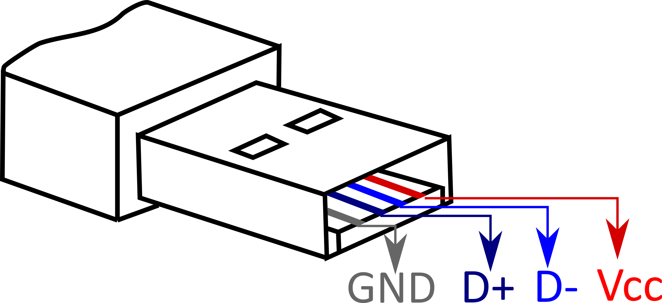
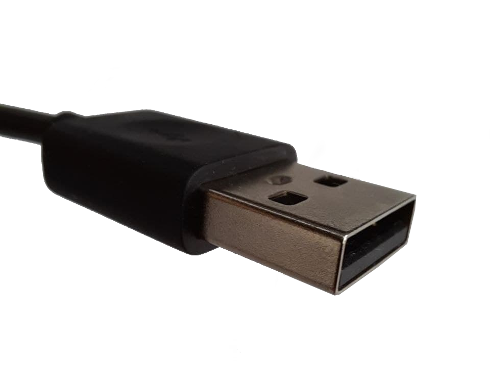
The interface consists of 4 pins: GROUND andSUPPLY VOLTAGE to act as a power supply, and +d and -d for serial communication. The supply voltage used to drive the devices ranges from 4.75V to 5.25V for normal operation, providing power to the connected device. The serial communication is transmitted in both directions by a twisted pair of cables, +d and -d. These conductors transmit data by applying voltage differences of approximately 3v in a process called differential signalling. This helps reduce the effects of noise on the signal. [2]
A USB device must identify itself, declaring its class (mass storage, printer, HID-Human Interface Device...) and subclass (gamepad, keyboard, flight controller...) so it can be handled accordingly. The device can then transfer data in 4 different ways:
- Control for managing the device, like its self-identification
- Bulk when large amounts of data need to be transmitted with disregard for even timing (e.g., mass storage)
- Interrupt for reacting to external events detected by the USB device (e.g., keyboards and gamepads)
- Isochronous when the continuity of data transmission needs to be guaranteed (e.g., audio players and webcams)
All these takes place between the host and up to 127 devices and USB hubs in a tree like structure.[2], [3]
Of course, this is just a shallow entry-level explanation, this subject is extremely deep and complex. In the Further Reading Section, I have provided some extra resources you can read to dive deeper into the USB standard.
Why can't you program any microcontroller to do it?
So, if the USB standard is so well documented and open source, why is there no Arduino library or PIC hex file to implement it? Why can't one just wire 2 GPIOs to +d and -d? The answer comes down to speed. Communications with microchips are usually carried out in the UART protocol, a series communication protocol with speeds ranging in the kb/sec [4]. USB communications at their slowest are in the order of Mb/sec, orders of magnitude higher[2]. To manage communications at those speeds special hardware needs to be used, USB interfacing needs to be hardware implemented.
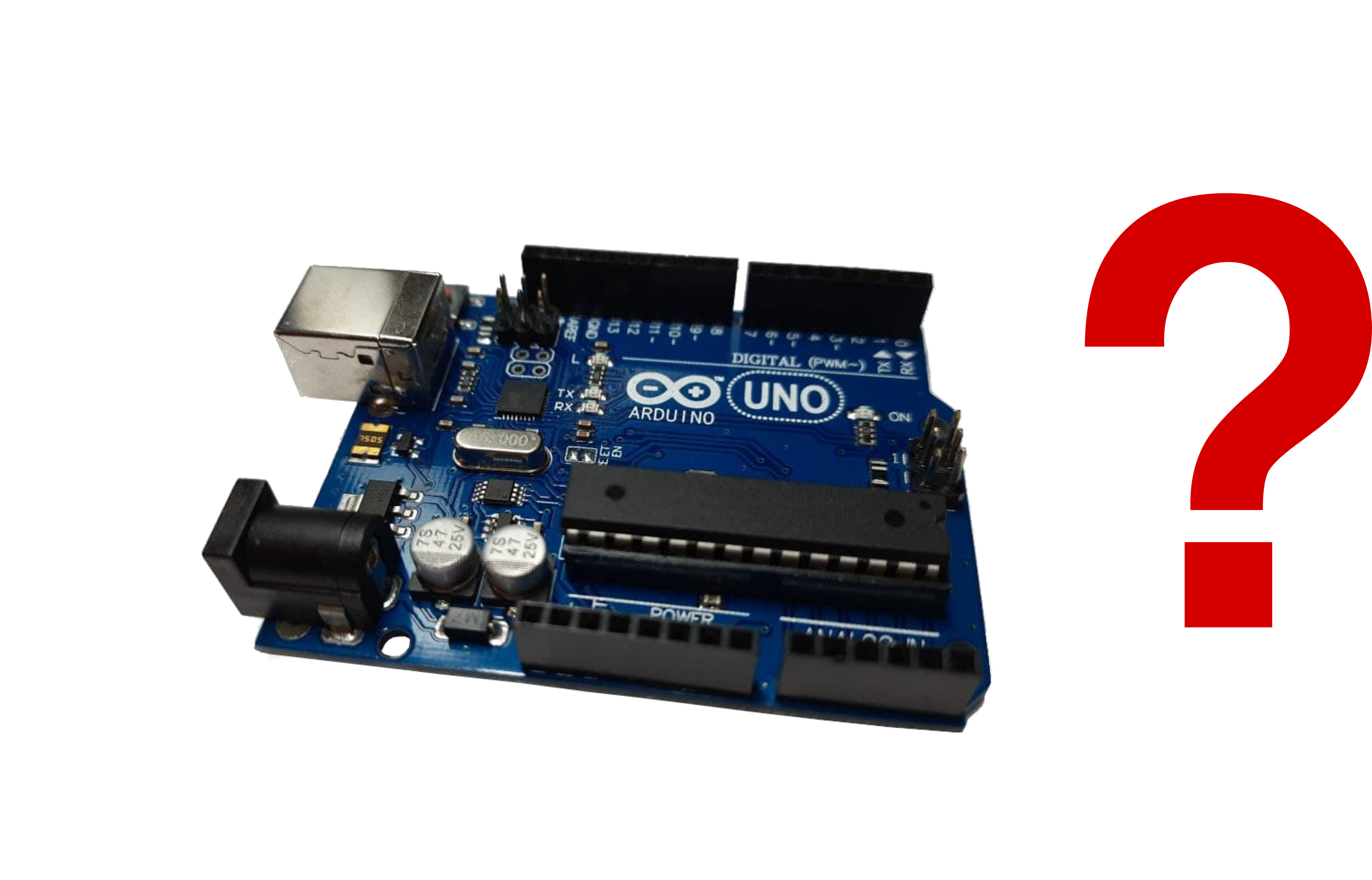
The solution for microcontrollers without built-in USB capabilities can be seen in the Arduino UNO. Its ATmega328p can be accessed through your computer USB thanks to another chip on the board with USB interfacing. Its purpose is to act as an UART to USB converter. Over the next sections I will discuss your options if you want to develop USB devices.
Using Arduino to make USB devices
Arduino development boards come in great variety and have a huge community. My recommendation is to follow this route and use a library such as the Joystick library. Here you have 3 options:
Option 1: Using the Arduino UNO
This is for you if you already own the Arduino UNO and wish not to spend any more money on other boards. For this you need to reprogram the UART-USB converter chip on the board. This can be done through the hoodloader.
Pros:
- Cheap
Cons:
- Tricky to use
- You must burn new firmware on to the board
- Bulky, you use the whole board so it cannot be minituarized effectively
Option 2: Using the Arduino LEONARDO or Arduino MICRO
If you opt to invest around 20€, you can use an Arduino board with the ATmega32u4 chip. This chip has a USB interface and can communicate directly with your computer or other devices through it. With the Arduino LEONARDO or MICRO, you can just plug in the board, load your code/library and you´re ready to go.
Pros:
- Easy to use
- Very small (for the LEONARDO you can take out the chip itself and use +d and -d pins for communication)
- Loads of resources available online
Cons:
- Pricey
Option 3: use Arduino equivalent boards
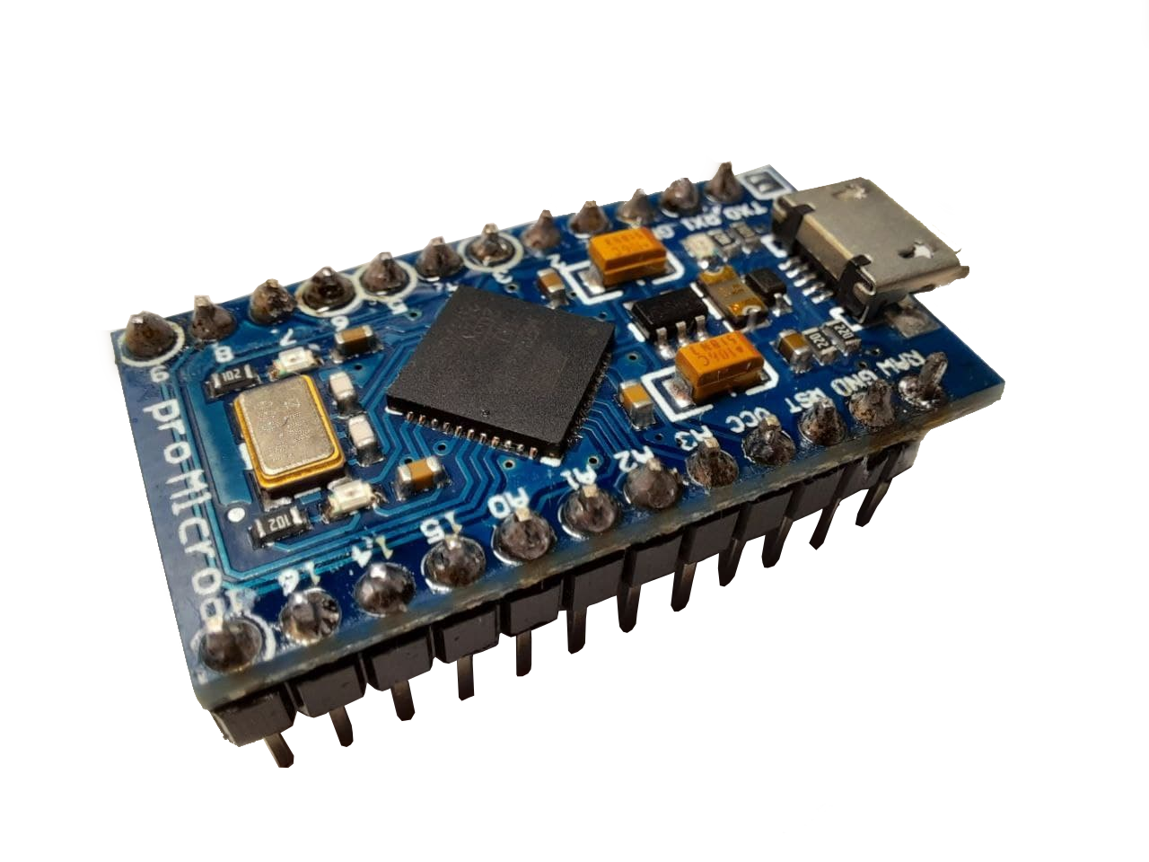
If you want a more budget friendly approach you may wish to buy an equivalent board that still uses the ATmega32u4 but for a lower price. Beware! Some Arduino MICRO clones actually have an ATmega328p and will not be useful for this, always check before buying. I personally use the KeeYees Pro Micro, it was 10€ when I bought it. You may also use more established brands like Teensy, but at a greater price.
Pros:
- Cheap
- Compatible with Arduino IDE
- Easy to use
- Small
Cons:
- Not much support available online for your specific board
Using a PIC as a USB device
You may want more control over your design and want to program on a lower level, closer to hardware level. In this case you can use a PIC. They are small, simple, and cheap but they are not entry level like Arduino boards. The options described below also apply to other chips such as those based on ARM you may want to use.
Option 1: Use a UART to USB converter
Just like the board on the Arduino UNO has a chip dedicated to communicating the USB to its ATmega328p, you can use an integrated UART to USB converter. Alternatively, you may implement the slow and easy to use RS 232 communication and get a USB-RS232 connector. These can be a bit pricey though, and they still run at the low speeds of UART.
Pros:
- You may use basically any chip
Cons:
- Pricey
- Space taken up by both the chip and the converter
- Low communication speed
Option 2: Find a microcontroller chip with integrated USB interface
You may find chips that already come with built-in USB interface. They tend to be more expensive than chips that come without it, but some are very budget friendly like the PIC16F1454. You will find official manufacturer documentation for the chip on how to use its USB interface.
Pros:
- All in one chip
- Easy to miniaturize
- Higher communication speeds than UART
Cons:
- Fewer choices of microcontroller to use
Further Reading
If you wish to dive deeper into the subjects introduced earlier, here are some useful links:
A - Some entry level information on USB communication
B - Good general information on USB protocol.
C - Official website for USB where you can find any information at a technical level.
D - Full official specification for USB 2.0. (not recommended for those who are beginners at electronics)
E - Page on how differential communication works.
F - Page explaining the basics of UART protocol for communication.
References
[1] "USB - Wikipedia." https://en.wikipedia.org/wiki/USB (accessed Apr. 03, 2021).
[2] C. H. Intel, L. Microsoft, and N. E. C. Philips, "Universal Serial Bus Specification," Group, 2000.
[3] "USB Operation: Protocol, Data Transfer & Packets » Electronics Notes." https://www.electronics-notes.com/articles/connectivity/usb-universal-serial-bus/protocol-data-transfer.php (accessed Apr. 03, 2021).
[4] "UART: A Hardware Communication Protocol Understanding Universal Asynchronous Receiver/Transmitter | Analog Devices." https://www.analog.com/en/analog-dialogue/articles/uart-a-hardware-communication-protocol.html (accessed Apr. 04, 2021).